YUV422 to RGB conversion using Python and OpenCV

In the previous post, we were garbing a RAW image from our camera using the v4l2-ctl tool. We were using a primitive Python script that allowed us to look at the Y channel. I decided to create yet another primitive script that enables the conversion of our YUV422 image into an RGB one.

import os
import sys
import cv2
import numpy as np

input_name = sys.argv[1]
output_name = sys.argv[2]
img_width = int(sys.argv[3])
img_height = int(sys.argv[4])


with open(input_name, "rb") as src_file:
    raw_data = np.fromfile(src_file, dtype=np.uint8, count=img_width*img_height*2)
    im = raw_data.reshape(img_height, img_width, 2)

    rgb = cv2.cvtColor(im, cv2.COLOR_YUV2BGR_YUYV)

    if output_name != 'cv':
        cv2.imwrite(output_name, rgb)
    else:
        cv2.imshow('', rgb)
        cv2.waitKey(0)

The OpenCV library does all image processing, so the only thing we need to do is to make sure we are passing the input data in the correct format. In the case of YUV422 we need to use an image with two channels: Y and UV.

Usage examples:

python3 yuv_2_rgb.py data.raw cv 3840 2160
python3 yuv_2_rgb.py data.raw out.png 3840 2160

Test with a webcam

You can check if your laptop camera supports YUYV by running the following command:

$ v4l2-ctl --list-formats-ext

If yes run following commands to get the RGB image. Please note that you might need to use different resolutions.

$ v4l2-ctl --set-fmt-video=width=640,height=480,pixelformat=YUYV --stream-mmap --stream-count=1 --device /dev/video0 --stream-to=data.raw
$ python3 yuv_2_rgb.py data.raw out.png 640 480

Test on the target

Time to convert the image coming from the i.MX8MP development board.

$ ssh root@imxdev
$$ v4l2-ctl --set-fmt-video=width=3840,height=2160,pixelformat=YUYV --stream-mmap --stream-count=1 --device /dev/video0 --stream-to=data.raw
$$ exit
$ scp root@imxdev:data.raw .
$ python3 yuv_2_rgb.py data.raw out.png 3840 2160
$ xdg-open out.png

Taking pictures with imx8mp-evk and Basler dart camera

Intro

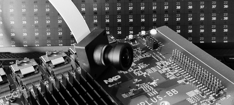
A new toy arrived: i.MX 8M Plus Evaluation board from NXP with a Basler 5MP camera module. This is going to be fun. Box opened. Cables connected. Power on. LEDs blinking. Time to take first picture.

Step 1. Check device tree

One thing we need for sure is a camera. Hardware is connected but does Linux know about it?

Nowadays, the Linux OS gets information about attached hardware out of a device tree*. This makes the configuration more flexible and does not require recompiling the kernel for every hardware change. NXP board BSP package already contains a device tree file for Basler camera so my only job is to check whatever it is used and enable it if not.

First we will check if the default device tree contains info about my camera. My system is up and running, so I can inspect the device tree by looking around in the sys directory. But first we need to know what are we looking for. If you open Basler device tree source file**, you can see that the camera is attached to the I2C bus:

...
#include "imx8mp-evk.dts"

&i2c2 {
	basler_camera_vvcam@36 {
...

If you now go to imx8mp.dtsi*** you discover that I2C2 is mapped to the address 30a30000.

...
    soc@0 {
	soc@0 {
		compatible = "simple-bus";
		#address-cells = <1>;
		#size-cells = <1>;
		ranges = <0x0 0x0 0x0 0x3e000000>;

		caam_sm: caam-sm@100000 {
			compatible = "fsl,imx6q-caam-sm";
			reg = <0x100000 0x8000>;
		};

		aips1: bus@30000000 {
			compatible = "simple-bus";
			reg = <0x30000000 0x400000>;
                ...
		aips3: bus@30800000 {
			compatible = "simple-bus";
			reg = <0x30800000 0x400000>;
			#address-cells = <1>;
			#size-cells = <1>;
			ranges;

			ecspi1: spi@30820000 {
                        ...
			i2c2: i2c@30a30000 {
				#address-cells = <1>;
				#size-cells = <0>;
				compatible = "fsl,imx8mp-i2c", "fsl,imx21-i2c";
				reg = <0x30a30000 0x10000>;
				interrupts = <GIC_SPI 36 IRQ_TYPE_LEVEL_HIGH>;
				clocks = <&clk IMX8MP_CLK_I2C2_ROOT>;


Lets check if this node is present on the target.

$ cd /sys/firmware/devicetree/base/soc@0/bus@30800000/i2c@30a30000
$ ls
#address-cells  adv7535@3d       clocks      interrupts              name            pinctrl-0      reg     tcpc@50
#size-cells     clock-frequency  compatible  lvds-to-hdmi-bridge@4c  ov5640_mipi@3c  pinctrl-names  status

Our camera is not listed there so its a device tree we need to fix first.

Step 2. Set device tree

To change device tree we need to jump into u-boot. Just restart the board and press any button when you see:
Hit any key to stop autoboot
Check and change boot-loader settings. First lets see what we have:

$ u-boot=> printenv
baudrate=115200                                                                 
board_name=EVK  
...
fastboot_dev=mmc2                                                               
fdt_addr=0x43000000                                                             
fdt_file=imx8mp-evk.dtb                                                         
fdt_high=0xffffffffffffffff                                                     
fdtcontroladdr=51bf7438                                                         
image=Image  
...
serial#=0b1f300028e99b32                                                        
soc_type=imx8mp                                                                 
splashimage=0x50000000                                                          
                                                                                
Environment size: 2359/4092 bytes  

As expected, u-boot uses the default device tree for our evaluation board. Let’s try to find the one with Basler camera config. I know it should sit in the eMMC, so I will start there.

$ u-boot=> mmc list
FSL_SDHC: 1
FSL_SDHC: 2 (eMMC)

$ u-boot=> mmc part

Partition Map for MMC device 2  --   Partition Type: DOS

Part    Start Sector    Num Sectors     UUID            Type
  1     16384           170392          a5b9776e-01     0c Boot
  2     196608          13812196        a5b9776e-02     83

$ u-boot=> fatls mmc 2:1
 29280768   Image
    56019   imx8mp-ab2.dtb
    61519   imx8mp-ddr4-evk.dtb
    61416   imx8mp-evk-basler-ov5640.dtb
    61432   imx8mp-evk-basler.dtb
    62356   imx8mp-evk-dsp-lpa.dtb
    62286   imx8mp-evk-dsp.dtb
    61466   imx8mp-evk-dual-ov2775.dtb
    61492   imx8mp-evk-ecspi-slave.dtb

We got it! Now its time to set is as a default one. And boot the board again.

$ u-boot=> setenv fdt_file imx8mp-evk-basler.dtb
$ u-boot=> saveenv                              
Saving Environment to MMC... Writing to MMC(2)... OK
$ u-boot=> boot

You can check in the directory we inspected last time that the camera hardware is present in the device tree.

Step 3. Get the image

Finally, we can get our image (a blob of pixels, to be clear). The easy way would be to connect the screen and run one of the NXP demo apps (though you need to flash your board with the full image to get them). But easy solutions are for people that do have their dev boards somewhere in the reach. Mine is running upstairs, and I prefer to do some extra typing than walking there. First, let’s check data formats supported by our camera.

$ v4l2-ctl --list-formats-ext
ioctl: VIDIOC_ENUM_FMT
        Type: Video Capture

        [0]: 'YUYV' (YUYV 4:2:2)
                Size: Discrete 3840x2160
                        Interval: Discrete 0.033s (30.000 fps)
        [1]: 'NV12' (Y/CbCr 4:2:0)
                Size: Discrete 3840x2160
                        Interval: Discrete 0.033s (30.000 fps)
        [2]: 'NV16' (Y/CbCr 4:2:2)
                Size: Discrete 3840x2160
                        Interval: Discrete 0.033s (30.000 fps)
        [3]: 'BA12' (12-bit Bayer GRGR/BGBG)
                Size: Discrete 3840x2160
                        Interval: Discrete 0.033s (30.000 fps)

We can grab a raw data using following command:

$ v4l2-ctl --set-fmt-video=width=3840,height=2160,pixelformat=YUYV --stream-mmap --stream-count=1 --device /dev/video0 --stream-to=data.raw
<
ls .
data.raw

Copy the raw data file to your development machine and execute this simple python script that will extract the Y component out of the YUV422 image:

# yuv_2_rgb (does not really convert but good enough to check if cam is working)
import sys
from PIL import Image

in_file_name = sys.argv[1]
out_file_name = sys.argv[2]

with open(in_file_name, "rb") as src_file:
    raw_data = src_file.read()
    img = Image.frombuffer("L", (3840, 2160), raw_data[0::2])
    img.save(out_file_name)


# RUN THIS ON YOUR DEV PC/MAC:
$ scp root@YOUR_BOARD_IP:data.raw .
$ python3 yuv_2_rgb.py data.raw data.bmp
$ xdg-open data.bmp

You should see a black and white image of whatever your camera was pointing at.

Step 4. Movie time

Now it is time to get some moving frames. I will use the GStreamer to send the image from the camera to my laptop with 2 simple commands:

# RUN THIS ON YOUR IMX EVALUATION BOARD (replace @YOUR_IP@ with your ip address): 
$ gst-launch-1.0 -v v4l2src device=/dev/video0 ! videoconvert ! videoscale ! videorate ! video/x-raw,framerate=30/1,width=320,height=240 ! vpuenc_h264 ! rtph264pay ! udpsink host=@YOUR_IP@ port=5000

# RUN THIS ON YOUR DEV PC/MAC:
$ gst-launch-1.0 udpsrc port=5000 !  application/x-rtp ! rtph264depay ! avdec_h264 ! autovideosink

That’s it. We can see the word through the i.MX eyes/sensors. You can play with the stream settings (image size, frame rate, etc.) or pump the data into some advanced image processing software. Whatever you do, have fun!


* if you are interested in the device trees, there are some great materials from Bootlin

** at the moment of writing the DTS for Basler camera can be found eg. here but since NXP is busy with de-Freescalization I expect it to be moved to some imx folder in the future

*** device trees are constructed in a hierarchical way and for our board imx8mp.dtsi is the top most one


Code monkey detected (in 80%)

The story begins with The Things Network Conference. Signed in. Got an Arduino Portenta board (inclusive camera shield) and attended an inspiring Edge Impulse workshop about building an embedded, machine learning based, elephant detector.

Finding elephants in my room is not a very useful thing. First: I never miss one if it shows up. Second: no elephant has ever shown up in my room. But there is a monkey. It eats one banana in the morning to get energy and one banana in the evening before it goes to bed*. Between eating its bananas, it sits, codes, drinks coffee, codes, makes some exercises and codes even more. Let’s detect this monkey and make a fortune by selling its presence information to big data companies.

Checklist

Four years ago, I half-finished “Machine Learning” online training (knowledge: checked). Once I run an out-of-the-box cat detection model with the Caffe framework (experience: checked). I read the book** (book: checked). I have no clue what I will be doing, but hey, that is how code monkeys do work.

Step one: get Arduino

I use an Arduino board, so I need an Arduino IDE. I follow the steps described here and have a working IDE. Now I probably need to install some extra stuff.

Step two: extra stuff

Following online tutorials, I add Portenta board (Tools->Board->Boards Managment, type “mbed”, install Arduino “mbed-enabled Boards” package). I struggle for some time with the camera example. The output image does not seem to be right. I am stuck for some time trying to figure out why the image height should be 244 instead of 240. The camera code looks like a very beta thing. Maybe I am just using the wrong package version. I switch from 1.3.1 to 1.3.2. Example works.

Next, I add TensorFlow library. Tools->Manage Libraries and type “tensor”. From the list, I install Arduino_TensorFlowLite.

Step three: run “Hello World”

The book starts with an elementary example, which uses machine learning to control PWM cycle of a LED light. This example targets Arduino Nano 33 BLE device, but apparently, it also works on Portena without any code modifications. I select, upload it and stay there watching as the LED changes its brightness.

Step four: detect the monkey

After some time of watching red LED, I am ready to do some actual coding. First I switch to the person detection example (File->Examples->Arduino_TensorFlowLite->person_detection). Then, I modify arduino_image_provider.cpp file, which contains GetImage function, which is used to get the image out of our camera. I throw away all its content and replace it with a modified version of the Portenta CameraCaptureRawBytes example:

#include <mbed.h>
#include "image_provider.h"
#include "camera.h"

const uint32_t cImageWidth = 320;
const uint32_t cImageHeigth = 240;
uint8_t sync[] = {0xAA, 0xBB, 0xCC, 0xDD};

CameraClass cam;
uint8_t buffer[cImageWidth * cImageHeigth];

// Get the camera module ready
void InitCamera(tflite::ErrorReporter* error_reporter) {
  TF_LITE_REPORT_ERROR(error_reporter, "Attempting to start Arducam");
  cam.begin();
}

// Get an image from the camera module
TfLiteStatus GetImage(tflite::ErrorReporter* error_reporter, int image_width,
                      int image_height, int channels, int8_t* image_data) {
  static bool g_is_camera_initialized = false;
  if (!g_is_camera_initialized) {
    InitCamera(error_reporter);
    g_is_camera_initialized = true;
  }

  cam.grab(buffer);
  Serial.write(sync, sizeof(sync));
  
  auto xOffset = (cImageWidth - image_width) / 2;
  auto yOffset = (cImageHeigth - image_height) / 2;
  
  for(int i = 0; i < image_height; i++) {
    for(int j = 0; j < image_width; j++) {
      image_data[(i * image_width) + j] = buffer[((i + yOffset) * cImageWidth) + (xOffset + j)];
    }
  }
    
  Serial.write(reinterpret_cast<uint8_t*>(image_data), image_width * image_height);

  return kTfLiteOk;
}

And a small change to the main program, so it shouts if the monkey is there.

...
  // Process the inference results.
  int8_t person_score = output->data.uint8[kPersonIndex];
  int8_t no_person_score = output->data.uint8[kNotAPersonIndex];

  if(person_score > 50 && no_person_score < 50) {
    TF_LITE_REPORT_ERROR(error_reporter, "MONKEY DETECTED!\n");
    TF_LITE_REPORT_ERROR(error_reporter, "Score %d %d.", person_score, no_person_score);
  }

I pass the image data to the model, and I send it via a serial port. I will use a simple OpenCV program to display my camera view (which can be useful when testing).

#include <opencv2/core.hpp>
#include <opencv2/highgui.hpp>
#include <opencv2/video.hpp>

#include <iostream>
#include <thread>

#include <boost/asio.hpp>
#include <boost/asio/serial_port.hpp>

using namespace cv;

const uint8_t cHeight = 96;
const uint8_t cWidth = 96;
uint8_t cSyncWord[] = {0xAA, 0xBB, 0xCC, 0xDD};

int main(int, char**)
{
    Mat frame, fgMask, back, dst;

    boost::asio::io_service io;
    boost::system::error_code error;

    auto port = boost::asio::serial_port(io);
    port.open("/dev/ttyACM0");
    port.set_option(boost::asio::serial_port_base::baud_rate(115200));

    std::thread t([&io]() {io.run();});

    while(true) {

        uint8_t buffer[cWidth * cHeight];

        uint8_t syncByte = 0;
        uint8_t currentByte;

        while (true) {

            boost::asio::read(port, boost::asio::buffer(&currentByte, 1));
            if (currentByte == cSyncWord[syncByte]) {
                syncByte++;
            } else {
                std::cerr << (char) currentByte;
                syncByte = 0;
            }
            if (syncByte == 4) {
                std::cerr << std::endl;
                break;
            }
        }

        boost::asio::read(port, boost::asio::buffer(buffer, cHeight * cWidth));

        frame = cv::Mat(cHeight, cWidth, CV_8U, buffer);

        if (frame.empty()) {
            std::cerr << "ERROR! blank frame grabbed" << std::endl;
            continue;
        }
        imshow("View", frame);

        if (waitKey(5) >= 0)
            break;
    }
    return 0;
}

I upload the script. Run the app. Point the camera at me. And… we got him! Monkey detected. I think I deserved a banana.

* bananas seem to possess some kind of fruit magic that makes them work according to user (eater) needs. Please google “boost your energy with banana” and “get better sleep with banana” if you want more details

** Tinyml: Machine Learning with Tensorflow Lite on Arduino and Ultra-Low-Power Microcontrollers by Pete Warden and Daniel Situnayake